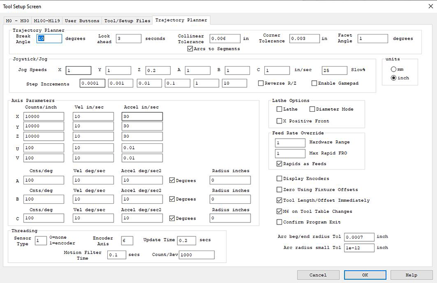
Tool Setup Screen - Trajectory Planner
(Click on image to jump to related help)
The Tool Setup Screen allows KMotionCNC to be configured for a particular machine tool. Each machine tool is likely to have different motion resolution, speeds, and acceleration limits. It is also likely to different I/O requirements with regard to Spindle control and such. Additionally a machine may have different initialization and homing requirements. KMotionCNC has a flexible mechanism for defining what type of action is to be performed for various M Codes and Custom Buttons. See here how to password-protect these parameters.
Trajectory Planner

KMotionCNC contains a powerful Trajectory Planner. The Trajectory Planner utilizes a "break angle" concept to decide when a stop must be made. Vectors that are in the same direction within the "break angle" are traversed without stopping. When a "sharp" angle is detected a complete stop will be made before beginning on the next vector. The Break Angle Parameter allows the user to specify the angle in degrees that will be considered a "sharp" angle. KMotionCNC considers the change in direction in 3 dimensions (x,y,z ignoring a). The Trajectory Planner is capable of optimizing the acceleration and deceleration through many short (or long) vectors all of which may have different acceleration and velocity limitations.
The Trajectory Planner also has a "lookahead" parameter. With KMotionCNC the G Code Program itself, the G Code Interpreter, and the Trajectory Planner all reside within the PC running Microsoft Windows™. Since the Microsoft Windows™ is not a real-time OS, a certain amount of motion must be buffered in the motion controller to handle the cases where the PC program doesn't have a chance to execute for a while. These time periods are typically very short (a few milliseconds), but in some extreme cases may occasionally be as long as one or several seconds. The worst case is often a factor of the hardware (disk network adapters, etc) and associated drivers that are loaded into the system. The lookahead parameter is used to determine how much motion, in terms of time, should be downloaded to the motion controller before actual motion is initiated. Furthermore, after motion has begun, the lookahead parameter is used to pause the trajectory planner to avoid having the Trajectory Planner get too far ahead of the actual motion. The disadvantage of having the Trajectory Planner get too far ahead is that if the User decides to override the feed rate, since the motion has already been planned and downloaded, the rate will not be changed quickly. A value of 3 seconds is very conservative on most systems. If more responsive feed rate override is desirable, an experiment with a smaller value might be made.
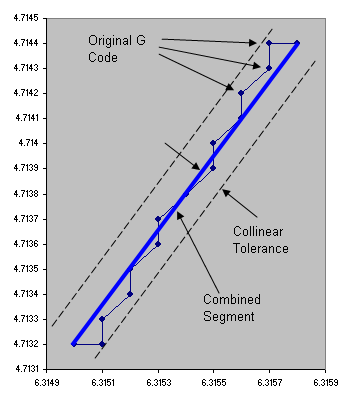
"Collinear Tolerance" allows GCode blocks that are nearly linear, to be combined into a single linear segment to allow faster and smoother motion. Often GCode programs generated by 3D CAD systems contain very small vectors that appear jagged or noisy due to numerical round off errors . See below for an example of a small GCode fragment from an intended circle. The 0.3 inch diameter circle was divided into 10,000 sides each only 0.0001 inches in length. Intuitively one would think this would result in an extremely smooth contour. Ironically, rounding off to 4 decimal digits introduces "noise" that results in sharp angles and each axis being required to repeatedly stop and start. Even with quite high acceleration, stopping and starting over short distances results in extremely low average speed and most likely a rough surface. A combined segment shown below in blue will result in a faster and smoother motion.
Segments are combined as long as all intermediate waypoints do not deviate from the combined segment by more than the allowed collinear tolerance. Setting the collinear tolerance to zero will disallow any segments from being combined.
	N70 G90 G54 G0 X6.315 Y4.7132 Z1.
	N100 G1 X6.3151 F60.
	N110 Y4.7133
	N120 X6.3152 Y4.7134
	N130 Y4.7135
	N140 X6.3153 Y4.7136
	N150 Y4.7137
	N160 X6.3154 Y4.7138
	N170 X6.3155 Y4.7139
	N180 Y4.714
	N190 X6.3156 Y4.7141
	N200 Y4.7142
	N210 X6.3157 Y4.7143
	N220 Y4.7144
	N230 X6.3158
The "Arcs To Segments" option allows circular arcs that were specified in the original GCode to be replaced by a number of linear segments. Each arc will be recursively subdivided until any cord error deviation from the original path is less than the Collinear Tolerance parameter. Sub dividing the arc (actually a helix) into line segments allows the path motion to be more fully optimized by the Trajectory Planner. This is because as the motion progresses through the arc the direction changes. As the direction changes the different axes become involved and also work together in different ways (diagonal directions make use of more than one axis). This means constraints (max velocity and acceleration) vary throughout the arc. With individual line segments the Trajectory planner is able to use optimal acceleration and velocity throughout the arc. When Arcs To Segments is not selected the entire arc may be treated as a single entity and will use the most limited velocity and acceleration constraints throughout the arc for the entire arc. If the feed rate is slow and curvature based accelerations are small relative to the axis limits then there will be little performance increase in using segments.
When the "Arcs To Segments" Option is selected the Collinear Tolerance must be larger than zero. Care should be used in selecting a Collinear Tolerance so that an excessive number of segments is not generated. The number of segments increases as the square root of the inverse of the Collinear Tolerance (cutting the tolerance in half increase the number of segments by 40%).
For a description of the Corner Rounding feature and Corner Tolerance and Facet Angle see here.
Jog Speeds

Defines the Jog Speeds for both the Jog Buttons and any attached Gamepad controller.These speeds are the maximum Jog speeds which are indicated by the outer jog arrow buttons (Jog Fast) or the GamePad joystick fully depressed. The user can define a slower speed as a percentage of the fast speed. See Also Jog Buttons.
Step Increments

Defines the step size distances for the Step Buttons that are displayed on the main KMotionCNC Screen. Setting a step size to zero will hide the size selection. The Enable Gamepad checkbox allows you to enable or disable a gamepad. Some systems falsely indicate that they have a gamepad installed, which may cause errors. In these cases, uncheck the Enable Gamepad checkbox. See Also Jog Buttons.
Units

Many of the parameters can be displayed as either inch or mm. However the 9 ABC parameters can be linear (inch or mm) or angular (degrees). The description of other cells are shown in inch mode, but by clicking the checkbox can be switched to mm mode. Also note that the units apply for this configuration screen only and do not apply for GCode and the Operator Screen.
Lathe Options

Defines options relating to Lathe systems.
Selecting the Lathe option orients the Jog Buttons and default GViewer orientations to have +Z horizontal to the right and with X vertical as most Lathe systems are configured. The "X Positive Front" rotates the axes system (and X Jog Keys) so that the tool moves toward the front of the system as X increases. This is more suitable for cutting tools mounted on the front side of the spindle. Otherwise the tool moves toward the back as X increases. This is more suitable for rear mounted tools.
X Positive Rear

X Positive Front
When Diameter Mode is selected the Gcode X Units, X Offset Units, and X DRO Units are all in terms of diameter. In this mode actual tool cutter motion is 1/2 the specified value so the the total diameter of the cut part is the specified value. When Diameter Mode is not selected, Radius mode will be used, the tool cutter motion will be the specified value, and the cut part will have a radius of the specified value in the GCode.
Feed Rate Override

The Hardware Range value allows control over what part of the Feed Rate Override (FRO) Range is handled by Hardware, and what part is handled by Software (Trajectory Planner).
Hardware FRO has the advantage of having instant response, however it has a disadvantage of having accelerations distorted by time warping. Accelerations will be distorted by the square of the FRO setting. For example a FRO of 2.0 will result in accelerations 4X higher than planned. Hardware FRO can be thought of like playing a movie back in fast or slow motion. Another analogy might be a car that plans a trajectory accelerating from 0 to 60MPH in 10 seconds. Played at double time (FRO=2.0) would result in acceleration from 0 to 120MPH in 5 seconds! Similarly feed rates through tight curves will be proportionally increased by the FRO possibly resulting in excessive acceleration. Velocities are also increased proportionally by the Hardware FRO. This is obviously the normal intention, however speeds at or near the maximum possible for the system may now exceed the capabilities of the system. This also applies for Rapid (G0) motions. Any Hardware FRO value higher than 1.0 must have maximum system settings set in a manner that accelerations and velocities have sufficient margins to allow this increased acceleration and velocity.
Hardware FRO values less than 1.0 will be distorted in the opposite manner. Accelerations will be unnecessarily slow. In the previous car analogy played at slow motion (FRO=0.5) the car would accelerate from 0 to 30MPH in 20 seconds. Motions through tight curves will be proportionally slowed down regardless if a higher speed might be possible and closer to the desired feed rate. Hardware FRO values less than 1.0 will never cause a maximum acceleration or velocity limit to be exceeded.
Software FRO always provides the optimal motion without ever exceeding any system constraint. Maximum Accelerations and Velocities on all axes will always be honored. Accelerations to feed rate will always be optimized. Speeds through curves will always be optimal. However such optimized Trajectory Planning is complex and requires look ahead and results in some delayed response to changes. Reducing lookahead can minimize this delay.
The FRO Hardware Range Parameter sets the boundary FRO value where values below the setting will be handled by Hardware, and values above the setting will be handled by Software. Here are some examples:
Hardware Range = 0.0 will cause all FRO values to be handled by Software.
Hardware Range = 100.0 (a huge value) will result in all FRO values being handled by Hardware.
Hardware Range = 1.0 will cause all values less than 1.0 to be handled by Hardware and values greater than 1.0 to be handled in Software. This is the largest value that will never cause the set values of Max Acceleration or Max Velocity set in the Trajectory Planner to be exceeded.
Hardware range = 1.2 will cause all values less than 1.2 to be handled by Hardware and values greater than 1.2 to be handled in Software. This setting is useful if it is required to have minor increases (+20%) and all decreases have an instant effect. However this requires that the set values of Max Acceleration or Max Velocity set in the Trajectory Planner be set by a factor of 1/1.22 = 0.69 of the system capabilities in order to provide margin to allow for the Hardware FRO.
Hardware Range = 0.5 will cause all values less than 0.5 to be handled by Hardware, and values greater than 0.5 to be handled in Software. In most cases this will result in a similar result as Hardware Range = 0.0 (with all changes handled by Software). However in cases for example where the FRO is suddenly reduced from 1.0 to 0.25 the system will first reduce the FRO to 0.5 in Software, and then the remainder, another factor of 0.5 in Hardware. The Software effect will be delayed but the hardware effect will be instant. This provides most all of the benefits of Software FRO in the normal ranges of (ie 0.9 - 1.1) while also allowing a means of instantly slowing down.
Max Rapid FRO
![]()
Limits the Rapid FRO to the specified value. Rapid FRO is always performed in hardware so values Rapid FRO values greater than 1.0 will exceed the specified Velocity, Acceleration, and Jerk specified in KFLOP. Use this limit to avoid FRO values that would cause Velocities, Accelerations, or Jerks that the system would be incapable of performing. This value is commonly set to 1.0 if the parameters specified in KFLOP are set at the maximum possible. To allow FRO values greater than 1.0 the system must have sufficient margin to be able to exceed the specified parameters. Values less than 1.0 are not commonly specified.
Rapids as Feeds
![]()
Selects whether Rapids are performed as 3rd-order (Jerk limited) motions or 2nd order Feed Motions. Most systems will not select this option so that Rapids are performed as faster/smoother 3rd-order Jerk-Limited motions. However KFLOP performs 3rd order Rapids as a single linear interpolated multi-axis motion at the actuator level. This is fine for normal Cartesian xyz linear systems however may cause problems for highly non-linear kinematic systems as a straight line in actuator space is not likely to be a straight line in real CAD space. For example a Delta Platform is an example of a non-linear system. This may result in a rapid motion path from one point to another to be along a somewhat unpredictable curved path. In some cases this may result in an undesirable crash. Geometric Correction is also a form of nonlinearity. However Geometric correction is usually not sufficiently non-linear to cause problems unless long rapids are performed passing very close to part surfaces or features. If nonlinearity is an issue for your system, select this option and Rapids will always be performed along a straight line as they will be subdivided into small segments where proper actuator positions are calculated to keep the motion along a straight line. Regardless of whether this option is selected or not the Velocity and Acceleration will be set by the KFLOP Axis Parameters not by the current GCode Feed Rate or Trajectory Planner Settings.
Display Encoders
![]()
Displays in the DROs the Measured Encoder Position for axes that are configured with an Input Mode other than None. When Un-checked all DROs display the commanded position.
Zero Using Fixture Offsets
![]()
Zero/Set Buttons near DROs allow the User to Set the DRO to Zero or a Specified Value. This is accomplished by adjusting GCode Offsets. When this option is selected then the currently selected Fixture Offset will be adjusted. When unchecked the Global G92/G52 Offset will be adjusted.
Tool Length/Offset Immediately
![]()
This option causes the KMotionCNC Drop Down Tool Selector to immediately select and apply the Tool Length (and offsets) Compensation without having to select and turn on the compensation in GCode with "HxxxxG43".
M6 on Tool Table Changes
This option causes the automatic execution of an TxxxM6 operation after the Tool Table has been edited to re-select the specified Tool so the selected Tool ID, slot, offsets, image all reflect the current state of the Tool Table.
Confirm Program Exit
![]()
By default checked, this option prompts a confirmation that a user wants to exit KMotionCNC.
Arc beg/end radius Tol
![]()
The GCode indirectly specifies the Start of the Arc (previous position), the End of the Arc (Specified Position), and the Arc Center Point (Previous Position + IJK offset). The distance between the Start to the Center and the End to the Center should be the same. Specifies the allowed Tolerance the GCode Interpreter will allow between the beginning and ending radius of an arc. This should be a very small number within the rounding tolerance of the numbers.
Arc radius small Tol
![]()
Tolerance parameter for allowing Arc Radius being smaller than half the distance from the start of Arc to End of Arc when specifying Arcs using R mode.
Axis Motion Parameters
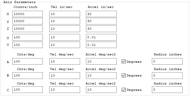
The Axis Motion Parameters define the scale, maximum feed velocities, and maximum feed accelerations for each of the six axis.
The first parameter is the axis's scale in counts/inch. For the example value of 100 shown, KMotionCNC will command the motion controller to move 100 counts for each inch of motion in the G Code Program. This value is always in counts/inch regardless of the units used in the interpreter. KMotionCNC will automatically perform any conversions.
The second parameter is the maximum allowed feed rate for the axis in inches/sec. Note that the G Code Interpreter Feed Rate is defined in inches per minute or (mm per minute) so be aware of the different time units. These are maximum feed rates for each axis. If a vector tool motion at a particular feed rate has any component velocity that exceeds the corresponding axis's maximum velocity, the feed rate for the vector will be reduced so that all axes remain at or below their maximum allowed velocity.
The third parameter is the maximum allowed acceleration for the axis in inches/sec2. The G Code Language has no provisions for specifying acceleration rates. Therefore the acceleration (and deceleration) along a vector used will always be the largest acceleration such that each axis's acceleration is at or below the specified limit.
The velocity and acceleration limits apply only to linear and circular feed motions (G1, G2, G3). Rapid motions (G0) use the settings in the motion controller (velocity, acceleration, and Jerk) to move all axes from one point to another along a straight line as quickly as possible without violating any axis involved in the motion constraints. To change the speed of G0 Rapid motions change the axes configuration settings in the motion controller.
Axes A,B,C sometimes are angular axes and are programmed to move angles of degrees rather than linear distances. If so select "Degrees" so that the axis moves in degrees regardless of the Inch or mm modes in GCode.
The best method for performing coordinated linear and angular combined motion is to use G93 Inverse Time Mode. This mode allows the CAD system to generate GCode that will cause the feed rate at the tool to always be at the desired feed rate based on the geometry of the system. However this requires a time (specified by its inverse) for each GCode block to be computed and included in the data stream. If Inverse TIme GCode data is not available a Radius for each Angular Axis can be specified. This allows the Trajectory planner to convert angular motion rates to linear motion rates. This assumes that the tool will remain at a relatively constant radius from the rotation axis (ie. engraving on a cylinder). Whenever Degrees is specified with a non-zero radius then the Trajectory Planner will consider the motion for that axis to be at the equivalent radius and orthogonal to all other combined motions.
As an example for the settings shown above for Axis A the maximum linear Velocity and Acceleration rates are the same as X, Y, and Z assuming a 10 inch radius about the A Axis of rotation.
57.295 deg/sec x π/180deg x 10in = 10in/sec
229.183 deg/sec2 x π/180deg x 10in = 40in/sec2
The GCode sequence shown below will perform a G1 Feed a linear distance of 10 inches in both X and A. Because the X and A axis are assumed to be orthogonal the combined distance will be assumed to be 14.1 inches total. At a feed rate of 60 ipm = 1 ips, the total Feed Time will be 14.1 sec (plus a small acceleration time).
G20
G0 X0 Y0 Z0 A0
G1 X10 A57.295 F60
M2
Threading/Spindle Settings
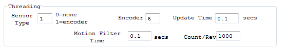
Spindle Speed measurement is supported as well as Single Point Threading. A quadrature encoder is required on the spindle. Specify the Sensor Type as 1 to enable the Spindle measurement. Configure the Axis Channel that is configured to read the encoder (Note this is not the encoder channel, rather it is the axis that has the encoder channel configured as its input). Specify the Update time, Tau, and counts/rev. See here for more information.