Tool Setup Screen - Files & Main Dialog Face
(Click on image to jump to related help)
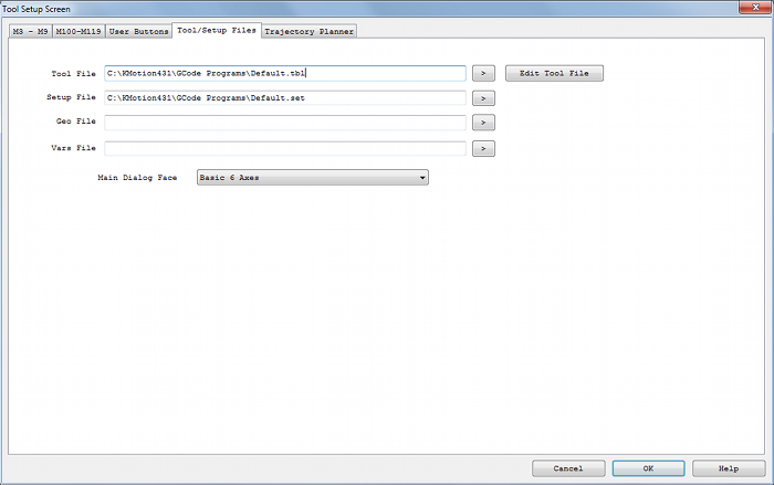
The Tool Setup Screen allows KMotionCNC to be configured for a particular machine tool. Each machine tool is likely to have different motion resolution, speeds, and acceleration limits. It is also likely to different I/O requirements with regard to Spindle control and such. Additionally a machine may have different initialization and homing requirements. KMotionCNC has a flexible mechanism for defining what type of action is to be performed for various M Codes and Custom Buttons. See here how to password-protect these parameters.
Tool Table File

The Tool Table File specifies the disk text file which contains the table of tool definitions. In some cases the G Code Interpreter needs to know the length and diameter of the selected tool for tool path compensation. This file is used to define up to 99 tools. See also Selecting Tools.
See below for an example Tool Table:
	POC FMS  LEN   DIAM  COMMENT

	1    1   0.0   0.0   first tool

	2    2   0.0   0.0

	3    3   1.0   0.5

	4    4   2.0   1.0

	32  32   0.0   0.0   last tool
Setup File

The Setup File specifies the disk text file which contains the setup table for the G Code Interpreter. In some machine tools the Interpreter may require a special initialization state. Below is the default Setup file. Modifications to the setup file should not normally be required.
  	Attribute                 Value       	Other Possible Values

  	axis_offset_x             0.0         	any real number
  	axis_offset_y             0.0         	any real number
  	axis_offset_z             0.0         	any real number
  	block_delete              ON          	OFF
  	current_x                 0.0         	any real number
  	current_y                 0.0         	any real number
  	current_z                 0.0         	any real number
  	cutter_radius_comp        OFF         	LEFT, RIGHT
  	cycle_r                   0.0         	any real number
  	cycle_z                   0.0         	any real number not less than cycle_r
  	distance_mode             ABSOLUTE    	INCREMENTAL
  	feed_mode                 PER_MINUTE  	INVERSE_TIME
  	feed_rate                 5.0         	any positive real number
  	flood                     OFF         	ON
  	length_units              MILLIMETERS 	INCHES
  	mist                      OFF         	ON
  	motion_mode               80          	0,1,2,3,81,82,83,84,85,86,97,88,89
  	plane                     XY          	YZ, ZX
  	slot_for_length_offset    1           	any unsigned integer less than 69
  	slot_for_radius_comp      1           	any unsigned integer less than 69
  	slot_in_use               1           	any unsigned integer less than 69
  	slot_selected             1           	any unsigned integer less than 69
  	speed_feed_mode           INDEPENDENT 	SYNCHED
  	spindle_speed             1000.0      	any non-negative real number
  	spindle_turning           STOPPED     	CLOCKWISE, COUNTERCLOCKWISE
  	tool_length_offset        0.0         	any non-negative real number
  	traverse_rate             199.0       	any positive real number
Geo File
![]()
Geometric correction file. Allows correcting errors in the the x,y,z positions. The callibration procedure involves moving the tool tip to an xy array of positions. For example, a precision grid might be printed on a glass or Mylar plate. By Jogging the tool tip to each row and column grid point and recording the machine's x,y,z position, a table of machine coordinates that correspond to perfect coordinates may be obtained. The "measure" button on the main KMotionCNC Screen may be used to log these positions. If such a table is specified here, the system will correct machine coordinates by bilinear xy interpolation of this table. Z is corrected for flatness at the plane of z=0 only.
The table format is shown below.
The first line specifies the number of rows and columns in the table.
The second line specifies the delta x and delta y between gridpoints.
The 3rd line defines any Table x,y offset. With an offset of 0,0 grid point row=0,col=0 will correspond to x=0, y=0. Specifying an offset will shift the table so that row=0, col=0 will correspond to the offset position. For example if the machine coordinates are such that the origin is in the middle of the range of travel, then a negative offset would be specified.
The remaining lines are row, column, x, y, z table entries.
For more information see here.
  	5	5
	1	1
	0	0
	0	0	-1.767822	-2.129132	-0.331770
	0	1	-0.878572	-2.068192	-0.262691
	0	2	 0.036983	-1.979272	-0.234576
	0	3	 0.930314	-1.909252	-0.237177
	0	4	 1.836404	-1.805593	-0.236061
	1	0	-1.774018	-1.155364	-0.219091
	1	1	-0.882401	-1.073801	-0.179651
	1	2	 0.021794	-0.987806	-0.141523
	1	3	 0.918408	-0.885504	-0.130446
	1	4	 1.792961	-0.811495	-0.124016
	2	0	-1.771149	-0.166872	-0.121132
	2	1	-0.883159	-0.075746	-0.074570
	2	2	 0.007254	 0.005231	-0.051105
	2	3	 0.889548	 0.097292	-0.035076
	2	4	 1.762710	 0.190093	-0.016807
	3	0	-1.761705	 0.784817	-0.086695
	3	1	-0.885633	 0.869580	-0.025417
	3	2	 0.001747	 1.008045	 0.017727
	3	3	 0.880585	 1.108997	 0.059038
	3	4	 1.742520	 1.204385	 0.058162
	4	0	-1.729192	 1.783193	 0.021364
	4	1	-0.871298	 1.868678	 0.054451
	4	2	 0.005017	 1.979718	 0.104414
	4	3	 0.878944	 2.104289	 0.141666
	4	4	 1.714383	 2.182679	 0.144980
Vars File
![]()
The Vars File is used to save all the GCode Variables which contain Fixture Offsets as well as other values. When Variables are saved to disk the file must already exist which lists which variables are to be saved. The file is read and all the variables present in the file will be replaced with their current values. Variables 5221-5226 contain the XYZABC coordinates of the first fixture offset. Skip 20 for each successive fixture.
Main Dialog Face
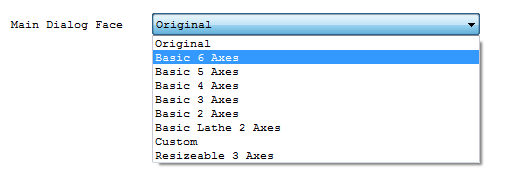
The Main Dialog Face selection selects the look of the main operation screen for KMotionCNC. Currently there are several available selections. The main difference is the number of axes, DROs and jog buttons. It is also possible to alter the dialogs by using a WindowsTM Resource Editor in Microsoft Visual Studio.
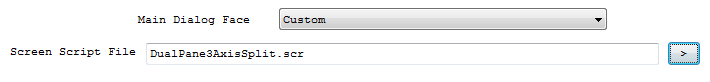
By selecting “Custom”, users can load cusom screen script files which can be created and modified using the KMotionCNC Screen Editor.