

Difference between revisions of "Kinematics"
From Dynomotion
m (Kinematics fix formatting and TOC) |
(→Kinematics GimbalCB and guide contributed by kizilkaya) |
||
| (7 intermediate revisions by the same user not shown) | |||
| Line 1: | Line 1: | ||
| + | ==Advantages of Kinematics and Rotation Tool Center Point (RTCP)== | ||
| + | RTCP takes into consideration the Kinematics of the machine to allow angular changes to the tool while keeping the tool center point at the same location relative to the machine table. Note this is true regardless of whether the Tool angle changes or the Table angle changes. The diagram below shows an example where the Tool angle is changed. | ||
| + | |||
| + | [[File:RTCP_On_Off.png|none|link=|670x350px]] | ||
| + | |||
| + | To perform RTCP an XYZ adjustment is applied to correct for XYZ shifts that occur with ABC angular changes. | ||
| + | |||
| + | |||
| + | |||
| + | For Gimbal Head type systems the Tool Tip location relative to the head pivot points must be known to compute the appropriate adjustments. This means that changes of Tool Lengths and Tool Offsets will affect the required adjustments. | ||
| + | |||
| + | |||
| + | |||
| + | For Trunnion Table table type systems the Tool Tip location relative to the Table pivot points must be known to compute the appropriate adjustments. This means that changes to GCode Offsets (Fixture/work or Global) will shift all the Tool Tip locations relative to the Table and will affect the required adjustments. | ||
| + | |||
| + | |||
| + | The data flow diagram below shows the difference between having a CAD system perform the Kinematics vs having the Controller perform the Kinematics. Having the Controller perform the Kinematics allows the same GCode to be used even though Tool Lengths, Work Offsets, or even Machine Geometries have been changed. | ||
| + | |||
| + | |||
| + | [[File:RTCP_Data_Flow.png|none|link=|770x550px]] | ||
| + | |||
| + | An additional advantage to having Kinematics performed in the Controller is that the Kinematics/RTCP is performed continuously throughout angular motions and not only on GCode Coordinates/Blocks/Lines. So for example in the case where only the B Axis is desired to rotate: | ||
| + | |||
| + | |||
| + | |||
| + | G0 B0 (start at angle 0) | ||
| + | |||
| + | G1 B90 (rotate B 90 degrees). | ||
| + | |||
| + | |||
| + | |||
| + | With RTCP in the Controller, only one line of GCode is required to rotate B 90degrees and throughout the motion the tool tip will remain in the same place. With RTCP in CAD, many lines of GCode would be required that include all the intermediate XYZ positions to keep the tool tip in the same place. | ||
| + | |||
| + | |||
| + | |||
| + | |||
| + | |||
==Overview== | ==Overview== | ||
Kinematics are part of the Coordinated Motion Library which is used by the GCode Interpreter. It provides a transformation from the desired CAD positions to the System's required Actuator positions to move there. | Kinematics are part of the Coordinated Motion Library which is used by the GCode Interpreter. It provides a transformation from the desired CAD positions to the System's required Actuator positions to move there. | ||
| Line 50: | Line 87: | ||
#include "Kinematics5AxisTableAC.h" | #include "Kinematics5AxisTableAC.h" | ||
#include "Kinematics5AxisTableBC.h"</pre> | #include "Kinematics5AxisTableBC.h"</pre> | ||
| − | |||
==Kinematics3Rod== | ==Kinematics3Rod== | ||
| Line 134: | Line 170: | ||
==A more complex 6 axis Kinematics (CKinematicsGeppetto)== | ==A more complex 6 axis Kinematics (CKinematicsGeppetto)== | ||
| − | |||
{{#ev:youtube|MSONYPXe3bE}} | {{#ev:youtube|MSONYPXe3bE}} | ||
| + | Formulas to calculate Actuator Positions from XYZABC CAD Position uses Rotate3 function to rotate a point through 3 angles. | ||
| + | |||
| + | <pre class="brush:c">int CKinematicsGeppettoExtrude::TransformCADtoActuators(double x, double y, double z, double a, double b, double c, double *Acts, bool NoGeo) | ||
| + | { | ||
| + | double x_0,y_0,z_0,x_1,y_1,z_1,x_2,y_2,z_2,x_3,y_3,z_3,x_4,y_4,z_4,x_5,y_5,z_5, TCP_Rotated_x,TCP_Rotated_y,TCP_Rotated_z; | ||
| + | // find lengths of each actuator | ||
| + | |||
| + | // Determine where the TCP rotated point would be relative to origin when oriented at the desired angles. | ||
| + | Rotate3(0, 0, 0, m_MotionParams.TCP_X, m_MotionParams.TCP_Y, m_MotionParams.TCP_Z, a, b, c, &TCP_Rotated_x, &TCP_Rotated_y, &TCP_Rotated_z); | ||
| + | |||
| + | // Translate from TCP to end effector origin | ||
| + | x += TCP_Rotated_x - m_MotionParams.TCP_X; | ||
| + | y += TCP_Rotated_y - m_MotionParams.TCP_Y; | ||
| + | z += TCP_Rotated_z - m_MotionParams.TCP_Z; | ||
| + | |||
| + | if (!NoGeo) GeoCorrect(x,y,z,a,b,c,&x,&y, &z, &a, &b, &c); | ||
| + | |||
| + | // Find where connection points should be | ||
| + | Rotate3(x,y,z,x+X0,y+Y0,z+Z0,a,b,c,&x_0,&y_0,&z_0); | ||
| + | Rotate3(x,y,z,x+X1,y+Y1,z+Z1,a,b,c,&x_1,&y_1,&z_1); | ||
| + | Rotate3(x,y,z,x+X2,y+Y2,z+Z2,a,b,c,&x_2,&y_2,&z_2); | ||
| + | Rotate3(x,y,z,x+X3,y+Y3,z+Z3,a,b,c,&x_3,&y_3,&z_3); | ||
| + | Rotate3(x,y,z,x+X4,y+Y4,z+Z4,a,b,c,&x_4,&y_4,&z_4); | ||
| + | Rotate3(x,y,z,x+X5,y+Y5,z+Z5,a,b,c,&x_5,&y_5,&z_5); | ||
| + | |||
| + | double r0 = sqrt(sqr(x_0 - Act0Center.x) + sqr(y_0 - Act0Center.y) + sqr(z_0 - Act0Center.z)) - Act0Off; | ||
| + | double r1 = sqrt(sqr(x_1 - Act1Center.x) + sqr(y_1 - Act1Center.y) + sqr(z_1 - Act1Center.z)) - Act1Off; | ||
| + | double r2 = sqrt(sqr(x_2 - Act2Center.x) + sqr(y_2 - Act2Center.y) + sqr(z_2 - Act2Center.z)) - Act2Off; | ||
| + | double r3 = sqrt(sqr(x_3 - Act3Center.x) + sqr(y_3 - Act3Center.y) + sqr(z_3 - Act3Center.z)) - Act3Off; | ||
| + | double r4 = sqrt(sqr(x_4 - Act4Center.x) + sqr(y_4 - Act4Center.y) + sqr(z_4 - Act4Center.z)) - Act4Off; | ||
| + | double r5 = sqrt(sqr(x_5 - Act5Center.x) + sqr(y_5 - Act5Center.y) + sqr(z_5 - Act5Center.z)) - Act5Off; | ||
| + | |||
| + | Acts[0] = r0*m_MotionParams.CountsPerInchX; | ||
| + | Acts[1] = r1*m_MotionParams.CountsPerInchY; | ||
| + | Acts[2] = r2*m_MotionParams.CountsPerInchZ; | ||
| + | Acts[3] = r3*m_MotionParams.CountsPerInchA; | ||
| + | Acts[4] = r4*m_MotionParams.CountsPerInchB; | ||
| + | Acts[5] = r5*m_MotionParams.CountsPerInchC; | ||
| + | |||
| + | return 0; | ||
| + | }</pre> | ||
==Alex's system with a Table A axis and Gimbal B axis (Kinematics5AxisTableAGimbalB.cpp)== | ==Alex's system with a Table A axis and Gimbal B axis (Kinematics5AxisTableAGimbalB.cpp)== | ||
| + | [[File:TableAGimbalBCAD.png|none|link=]] | ||
{{#ev:youtube|PuIdtZKdYfA}} | {{#ev:youtube|PuIdtZKdYfA}} | ||
| Line 156: | Line 233: | ||
| − | The code: | + | The formula in C++ code: |
| Line 203: | Line 280: | ||
} | } | ||
</pre> | </pre> | ||
| + | |||
| + | ==Scara Robot Kinematics by Demondor== | ||
| + | See Forum Thread with code [https://www.dynomotion.com/forum/viewtopic.php?f=10&t=922 here]. | ||
| + | |||
| + | |||
| + | Geometry below | ||
| + | |||
| + | [[File:ScaraGeometry.png|none|link=]] | ||
| + | |||
| + | Class name CKinematicsScara | ||
| + | |||
| + | |||
| + | |||
| + | ==2 Axis Spray Robot by Scott Little== | ||
| + | Simulation | ||
| + | |||
| + | {{#ev:youtube|veQftMBxbzU}} | ||
| + | {{#ev:youtube|eon96CIPQkY}} | ||
| + | |||
| + | Forum Thread [https://dynomotion.com/forum/viewtopic.php?f=16&t=1182 here]. | ||
| + | |||
| + | Class Name CKinematics2AxisRobot | ||
| + | |||
| + | |||
| + | |||
| + | 3 Axis Cable Delta Robot by Александр Украинец== | ||
| + | |||
| + | {{#ev:youtube|1LG6tnt08wE}} | ||
| + | |||
| + | Class Name CKinematics3axisDeltaRobot | ||
| + | |||
| + | Project Details | ||
| + | |||
| + | [https://docs.google.com/document/d/1FLZXM_LQojO0Z4cQUFxOFcynNfsAr4oe34-rbIXFz8E/edit?usp=sharing Shared Project Files] | ||
| + | |||
| + | ==5 Axis Gimbal CB by Forum User kizilkaya== | ||
| + | |||
| + | {{#ev:youtube|US-MbuuB5U8}} | ||
| + | |||
| + | Class Name CKinematicsGimbalCB | ||
| + | |||
| + | |||
| + | Here is an RTCP Guide submitted by kizilkaya | ||
| + | |||
| + | |||
| + | There is a lot of complicated information about RTCP and it took me a long time to collect all this and deliver the machine to my customer, but I finally succeeded. RTCP works without any problems. I have prepared a detailed guide for those who do not want to experience difficulties like me. I would be happy if you share it.<br /><br />STEP 1 ) Adjust all axis settings very precisely, especially the angled axes.<br /><br />STEP 2 ) Kinematics.txt from Data.rar copy to C:\KMotion5.3.4\GCodeInterpreter<br /><br />STEP 3 ) Select Kinematic from Kinematics.txt according to your machine configuration. (e.g. Kinematics5AxisGimbalCB).<br /><br />STEP 4 )B and C axis positions must be set to "0 (zero)" as shown in the picture, otherwise the angled axes will tilt in different directions when RTCP is active.<br /><br />STEP 5 ) Open the C:\KMotion5.3.4\GCodeInterpreter\GCodeInterpreter.vcxproj file with Visual Studio and set the pivot as seen in the pivot.png image, then compile the project and create the GCodeInterpreter element.<br /><br />Now you can use rctp actively with "G43.4 Hx (x tool number)" and turn off rtcp with "G49".<br /><br />Example ;<br />Please first pull the x, y and z axes (taking the pivot length into consideration) to a safe area and edit the g code according to the C and B axis limits.<br /><br />G43.4 H1 G1 F3000 B0 C0<br />B90<br />B-90<br />C-180<br />C180<br />B0 C0<br />M30 | ||
| + | |||
| + | |||
| + | [[File:pivot.png|none|link=|958x393px]] | ||
| + | |||
| + | |||
| + | [[File:Cosmeq.jpeg|none|link=|768x432px]] | ||
| + | |||
| + | |||
| + | Download Project [[Media:5AxisGimbalCBFiles.zip|Files]] | ||
Latest revision as of 20:12, 4 September 2024
Contents
- 1 Advantages of Kinematics and Rotation Tool Center Point (RTCP)
- 2 Overview
- 3 Kinematics3Rod
- 4 A more complex 6 axis Kinematics (CKinematicsGeppetto)
- 5 Alex's system with a Table A axis and Gimbal B axis (Kinematics5AxisTableAGimbalB.cpp)
- 6 Scara Robot Kinematics by Demondor
- 7 2 Axis Spray Robot by Scott Little
- 8 5 Axis Gimbal CB by Forum User kizilkaya
Advantages of Kinematics and Rotation Tool Center Point (RTCP)
RTCP takes into consideration the Kinematics of the machine to allow angular changes to the tool while keeping the tool center point at the same location relative to the machine table. Note this is true regardless of whether the Tool angle changes or the Table angle changes. The diagram below shows an example where the Tool angle is changed.

To perform RTCP an XYZ adjustment is applied to correct for XYZ shifts that occur with ABC angular changes.
For Gimbal Head type systems the Tool Tip location relative to the head pivot points must be known to compute the appropriate adjustments. This means that changes of Tool Lengths and Tool Offsets will affect the required adjustments.
For Trunnion Table table type systems the Tool Tip location relative to the Table pivot points must be known to compute the appropriate adjustments. This means that changes to GCode Offsets (Fixture/work or Global) will shift all the Tool Tip locations relative to the Table and will affect the required adjustments.
The data flow diagram below shows the difference between having a CAD system perform the Kinematics vs having the Controller perform the Kinematics. Having the Controller perform the Kinematics allows the same GCode to be used even though Tool Lengths, Work Offsets, or even Machine Geometries have been changed.

An additional advantage to having Kinematics performed in the Controller is that the Kinematics/RTCP is performed continuously throughout angular motions and not only on GCode Coordinates/Blocks/Lines. So for example in the case where only the B Axis is desired to rotate:
G0 B0 (start at angle 0)
G1 B90 (rotate B 90 degrees).
With RTCP in the Controller, only one line of GCode is required to rotate B 90degrees and throughout the motion the tool tip will remain in the same place. With RTCP in CAD, many lines of GCode would be required that include all the intermediate XYZ positions to keep the tool tip in the same place.
Overview
Kinematics are part of the Coordinated Motion Library which is used by the GCode Interpreter. It provides a transformation from the desired CAD positions to the System's required Actuator positions to move there.
To add new Kinematics a new C++ Kinematics Class will be required to be added to the GCodeInterpreter Project. See here for information on modifying and building the KMotion Libraries and PC Examples.
Normally only equations for inverse kinematics (determines Actuator positions from given CAD position) are required to be defined. The CKinematics class will automatically solve forward kinematics numerically.
A text file (Kinematics.txt) in the in the <>\KMotion\Data directory contains a string that is used by the CCoordMotion class to determine what Kinematics Class is to be used. If the text file doesn't exist standard, orthogonal, linear Kinematics are used.
After adding your new kinematics class a test for your new class should be added to CoordMotion.cpp into the code shown below. Also the appropriate string should be placed into the Kinematics.txt file. Additional parameters might be included in this file to be read by your Kinematics Class to make it more general.
	FILE *f = fopen((CString)MainPath + "\\Data\\Kinematics.txt","rt");

	if (f)
	{
		char s[81];
		fgets(s, 80, f);
		// one exists, check if it is calling for Geppetto otherwise assume it is the 3Rod

		if (strstr(s, "5AxisTableAC") != NULL)
			Kinematics = new CKinematics5AxisTableAC;
		else if (strstr(s, "5AxisTableBC") != NULL)
			Kinematics = new CKinematics5AxisTableBC;
		else if (strstr(s, "5AxisGimbalAB") != NULL)
			Kinematics = new CKinematics5AxisGimbalAB;
		else if (strstr(s, "5AxisGimbalCB") != NULL)
			Kinematics = new CKinematics5AxisGimbalCB;
		else if (strstr(s, "GeppettoExtruder") != NULL)
			Kinematics = new CKinematicsGeppettoExtrude;
		else if (strstr(s, "Geppetto") != NULL)
			Kinematics = new CKinematicsGeppetto;
		else
			Kinematics = new CKinematics3Rod;

		fclose(f);
	}
Note: In order for your new class to be defined its header file should be added into the standard header include file StdAfx.h in the GCodeInterpreter Directory as are the other Kinematic class headers as shown below:
#include "Kinematics.h"
#include "Kinematics3Rod.h"
#include "KinematicsGeppetto.h"
#include "KinematicsGeppettoExtrude.h"
#include "Kinematics5AxisGimbalAB.h"
#include "Kinematics5AxisGimbalCB.h"
#include "Kinematics5AxisTableAC.h"
#include "Kinematics5AxisTableBC.h"
Kinematics3Rod
The first non-linear Kinematics that was added to the KMotion Libraries was the simple Kinematics3Rod class shown below. Given the XYZ CAD position it computes the necessary lengths of 3 "rod" type linear actuators to place the end effector at the desired CAD location. Also below is a old video of it in operation.
	// Kinematics3Rod.cpp: implementation of the CKinematics3Rod class.
//
//////////////////////////////////////////////////////////////////////

#include "stdafx.h"
#include "Kinematics3Rod.h"

#define sqr(x) ((x)*(x))


//////////////////////////////////////////////////////////////////////
// Construction/Destruction
//////////////////////////////////////////////////////////////////////

CKinematics3Rod::CKinematics3Rod()
{
	Act0Center.x = 12;
	Act0Center.y = 0;
	Act0Center.z = 0;

	Act1Center.x = 0;
	Act1Center.y = 12;
	Act1Center.z = 0;

	Act2Center.x = 11;
	Act2Center.y = 3;
	Act2Center.z = 12;

	// when actuator position is zero this is how long the rod is

	Act0Off = sqrt(sqr(Act0Center.x) + sqr(Act0Center.y) + sqr(Act0Center.z));
	Act1Off = sqrt(sqr(Act1Center.x) + sqr(Act1Center.y) + sqr(Act1Center.z));
	Act2Off = sqrt(sqr(Act2Center.x) + sqr(Act2Center.y) + sqr(Act2Center.z));

	m_MotionParams.MaxLinearLength = 0.25;  // limit the segment lengs for nonlinear systems
	m_MotionParams.MaxRapidFRO = 1.0;       // limit the increase in Rapid HW FRO
	m_MotionParams.UseOnlyLinearSegments=true;
}

CKinematics3Rod::~CKinematics3Rod()
{

}

int CKinematics3Rod::TransformCADtoActuators(double x, double y, double z, double a, double b, double c, double *Acts, bool NoGeo)
{
	// find lengths of each actuator

	GeoCorrect(x,y,z,&x,&y,&z);

	double r0 = sqrt(sqr(x-Act0Center.x) + sqr(y-Act0Center.y) + sqr(z-Act0Center.z)) - Act0Off;
	double r1 = sqrt(sqr(x-Act1Center.x) + sqr(y-Act1Center.y) + sqr(z-Act1Center.z)) - Act1Off;
	double r2 = sqrt(sqr(x-Act2Center.x) + sqr(y-Act2Center.y) + sqr(z-Act2Center.z)) - Act2Off;

	Acts[0] = r0*m_MotionParams.CountsPerInchX;
	Acts[1] = r1*m_MotionParams.CountsPerInchY;
	Acts[2] = r2*m_MotionParams.CountsPerInchZ;

	Acts[3] = a*m_MotionParams.CountsPerInchA;
	Acts[4] = b*m_MotionParams.CountsPerInchB;
	Acts[5] = c*m_MotionParams.CountsPerInchC;

	return 0;
}


// perform Inversion to go the other way

int CKinematics3Rod::TransformActuatorstoCAD(double *Acts, double *xr, double *yr, double *zr, double *ar, double *br, double *cr, bool NoGeo)
{
	return InvertTransformCADtoActuators(Acts, xr, yr, zr, ar, br, cr);
}
A more complex 6 axis Kinematics (CKinematicsGeppetto)
Formulas to calculate Actuator Positions from XYZABC CAD Position uses Rotate3 function to rotate a point through 3 angles.
int CKinematicsGeppettoExtrude::TransformCADtoActuators(double x, double y, double z, double a, double b, double c, double *Acts, bool NoGeo)
{
	double x_0,y_0,z_0,x_1,y_1,z_1,x_2,y_2,z_2,x_3,y_3,z_3,x_4,y_4,z_4,x_5,y_5,z_5, TCP_Rotated_x,TCP_Rotated_y,TCP_Rotated_z;
	// find lengths of each actuator

	// Determine where the TCP rotated point would be relative to origin when oriented at the desired angles.
	Rotate3(0, 0, 0, m_MotionParams.TCP_X, m_MotionParams.TCP_Y, m_MotionParams.TCP_Z, a, b, c, &TCP_Rotated_x, &TCP_Rotated_y, &TCP_Rotated_z);

	// Translate from TCP to end effector origin
	x += TCP_Rotated_x - m_MotionParams.TCP_X;
	y += TCP_Rotated_y - m_MotionParams.TCP_Y;
	z += TCP_Rotated_z - m_MotionParams.TCP_Z;

	if (!NoGeo) GeoCorrect(x,y,z,a,b,c,&x,&y, &z, &a, &b, &c);

	// Find where connection points should be
	Rotate3(x,y,z,x+X0,y+Y0,z+Z0,a,b,c,&x_0,&y_0,&z_0);
	Rotate3(x,y,z,x+X1,y+Y1,z+Z1,a,b,c,&x_1,&y_1,&z_1);
	Rotate3(x,y,z,x+X2,y+Y2,z+Z2,a,b,c,&x_2,&y_2,&z_2);
	Rotate3(x,y,z,x+X3,y+Y3,z+Z3,a,b,c,&x_3,&y_3,&z_3);
	Rotate3(x,y,z,x+X4,y+Y4,z+Z4,a,b,c,&x_4,&y_4,&z_4);
	Rotate3(x,y,z,x+X5,y+Y5,z+Z5,a,b,c,&x_5,&y_5,&z_5);

	double r0 = sqrt(sqr(x_0 - Act0Center.x) + sqr(y_0 - Act0Center.y) + sqr(z_0 - Act0Center.z)) - Act0Off;
	double r1 = sqrt(sqr(x_1 - Act1Center.x) + sqr(y_1 - Act1Center.y) + sqr(z_1 - Act1Center.z)) - Act1Off;
	double r2 = sqrt(sqr(x_2 - Act2Center.x) + sqr(y_2 - Act2Center.y) + sqr(z_2 - Act2Center.z)) - Act2Off;
	double r3 = sqrt(sqr(x_3 - Act3Center.x) + sqr(y_3 - Act3Center.y) + sqr(z_3 - Act3Center.z)) - Act3Off;
	double r4 = sqrt(sqr(x_4 - Act4Center.x) + sqr(y_4 - Act4Center.y) + sqr(z_4 - Act4Center.z)) - Act4Off;
	double r5 = sqrt(sqr(x_5 - Act5Center.x) + sqr(y_5 - Act5Center.y) + sqr(z_5 - Act5Center.z)) - Act5Off;

	Acts[0] = r0*m_MotionParams.CountsPerInchX;
	Acts[1] = r1*m_MotionParams.CountsPerInchY;
	Acts[2] = r2*m_MotionParams.CountsPerInchZ;
	Acts[3] = r3*m_MotionParams.CountsPerInchA;
	Acts[4] = r4*m_MotionParams.CountsPerInchB;
	Acts[5] = r5*m_MotionParams.CountsPerInchC;

	return 0;
}
Alex's system with a Table A axis and Gimbal B axis (Kinematics5AxisTableAGimbalB.cpp)

Here is the math. First the definitions:

Origin Definition

The Solution

The formula in C++ code:
// Kienematics for Table with A Axis and Tool Gimble head with B Axis
//
// A axis always rotates about X axis
// B axis always rotates about Y axis

int CKinematics5AxisTableAGimbalB::TransformCADtoActuators(double x, double y, double z, double a, double b, double c, double *Acts, bool NoGeo)
{
	double Xt, Yt, Zt, Xa, Ya, Za, ToolXR, ToolZR, ChuckXR, ChuckZR, Dummy;


	if (m_MotionParams.TCP_Active)
	{
		//Find CAD Tool Tip Location from coordinate passed in (Xt, Yt, Zt)
		Xt = x - m_MotionParams.TCP_X;  // remove tool offset
		Yt = y - m_MotionParams.TCP_Y;
		Zt = z - m_MotionParams.TCP_Z;

		//Perform A rotation to obtain (Xa, Ya, Za)
		Rotate3(0, 0, 0, Xt, Yt, Zt, a, 0, 0, &Xa, &Ya, &Za);

		//Determine ChuckXR ChuckZR by rotating PivotChuckLength by Angle B
		Rotate3(0, 0, 0, 0, 0, PivotToChuckLength, 0, -b, 0, &ChuckXR, &Dummy, &ChuckZR);

		//Determine Rotated Tool offset ToolXR ToolZR by rotating ToolX ToolZ by Angle B
		Rotate3(0, 0, 0, m_MotionParams.TCP_X, m_MotionParams.TCP_Y, m_MotionParams.TCP_Z, 0, -b, 0, &ToolXR, &Dummy, &ToolZR);

		x = Xa + ToolXR + ChuckXR;
		y = Ya;
		z = Za + ToolZR + ChuckZR - PivotToChuckLength;
	}

	if (!NoGeo) GeoCorrect(x,y,z,&x,&y, &z);

	Acts[0] = x*m_MotionParams.CountsPerInchX;
	Acts[1] = y*m_MotionParams.CountsPerInchY;
	Acts[2] = z*m_MotionParams.CountsPerInchZ;
	Acts[3] = a*m_MotionParams.CountsPerInchA;
	Acts[4] = b*m_MotionParams.CountsPerInchB;
	Acts[5] = c*m_MotionParams.CountsPerInchC;

	return 0;
}
Scara Robot Kinematics by Demondor
See Forum Thread with code here.
Geometry below
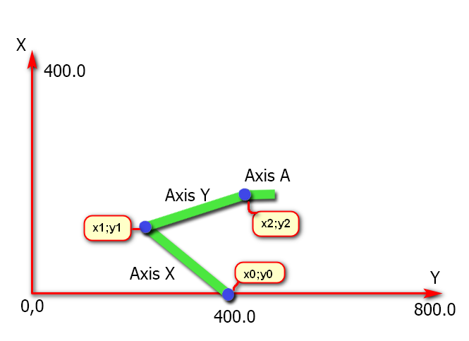
Class name CKinematicsScara
2 Axis Spray Robot by Scott Little
Simulation
Forum Thread here.
Class Name CKinematics2AxisRobot
3 Axis Cable Delta Robot by Александр Украинец==
Class Name CKinematics3axisDeltaRobot
Project Details
5 Axis Gimbal CB by Forum User kizilkaya
Class Name CKinematicsGimbalCB
Here is an RTCP Guide submitted by kizilkaya
There is a lot of complicated information about RTCP and it took me a long time to collect all this and deliver the machine to my customer, but I finally succeeded. RTCP works without any problems. I have prepared a detailed guide for those who do not want to experience difficulties like me. I would be happy if you share it.
STEP 1 ) Adjust all axis settings very precisely, especially the angled axes.
STEP 2 ) Kinematics.txt from Data.rar copy to C:\KMotion5.3.4\GCodeInterpreter
STEP 3 ) Select Kinematic from Kinematics.txt according to your machine configuration. (e.g. Kinematics5AxisGimbalCB).
STEP 4 )B and C axis positions must be set to "0 (zero)" as shown in the picture, otherwise the angled axes will tilt in different directions when RTCP is active.
STEP 5 ) Open the C:\KMotion5.3.4\GCodeInterpreter\GCodeInterpreter.vcxproj file with Visual Studio and set the pivot as seen in the pivot.png image, then compile the project and create the GCodeInterpreter element.
Now you can use rctp actively with "G43.4 Hx (x tool number)" and turn off rtcp with "G49".
Example ;
Please first pull the x, y and z axes (taking the pivot length into consideration) to a safe area and edit the g code according to the C and B axis limits.
G43.4 H1 G1 F3000 B0 C0
B90
B-90
C-180
C180
B0 C0
M30


Download Project Files