

Difference between revisions of "Main Page"
From Dynomotion
m (→Installation Topics) |
(→Multiplexing Encoder Inputs to KFLOP JP4 and JP6) |
||
| Line 230: | Line 230: | ||
[[File:NPN_Interface_to_KFLOP.png|none|link=|544x544px]] | [[File:NPN_Interface_to_KFLOP.png|none|link=|544x544px]] | ||
| + | |||
| + | |||
| + | |||
| + | ====Multiplexing Encoder Inputs to KFLOP JP4 and JP6==== | ||
| + | If KFLOP JP7 and JP5 are used for other purposes the encoder inputs can be multiplexed to KFLOP JP4 and JP6. There is an option to multiplex encoders 0-3 from JP7 to JP4 and another option to multiplex encoders 4-7 from JP5 to JP6. See the MuxEncoders.c for an example. | ||
| + | |||
| + | Note the JP4 and JP6 IO are 3.3V inputs and shouldn't be driven hard (more than 10ma) above 3.8V. This is not usually an issue as most encoders or RS422 drivers don't do this. The inputs also have 150 ohm termination. | ||
| + | |||
| + | The following line of code might be added to your Initialization C Program. It needs to be executed once to multiplex the encoders after any power cycle. Encoders 0-3 will then be input on JP4 and 4-7 will be on JP6. Both JP4 and Jp6 have 10 IO bits. The 4 encoders will appear on the first 8 IO bits. 2 bits for each encoder's A B channels in order. So for example Encoder #0 will appear on JP4 IO16 (Pin5) and IO17 (Pin6) | ||
| + | |||
| + | <pre class="brush:c"> | ||
| + | // Mux encoder inputs from KFLOP JP7 & JP5 to JP4 and JP6 | ||
| + | FPGAW(ENC_NOISE_FILTER_ADD) = ENC_0_3_JP4 + ENC_4_7_JP6 + ENC_NOISE_FILTER_DEFAULT_VAL; </pre> | ||
| + | |||
| + | JP4 and JP6 have +5V available on Pin1 and GND on Pins 8 and 9 that might be used to power 5V encoders. | ||
==<span id="Axes_Servo_Tuning_and_Trajectory_Planner" class="mw-headline">Axes Servo Tuning and Trajectory Planner</span>== | ==<span id="Axes_Servo_Tuning_and_Trajectory_Planner" class="mw-headline">Axes Servo Tuning and Trajectory Planner</span>== | ||
Revision as of 21:30, 28 February 2019
Contents
- 1 Dynomotion wiki
- 2 Editing and Creating Wiki Pages
- 3 Dynomotion Software Topics
- 3.1 Installation Topics
- 3.2 KMotion.exe Executive Software Topics
- 3.3 Configuration Topics
- 3.4 KMotionCNC Software Topics
- 3.5 PC Example Applications
- 3.6 KMotion Libraries - GCode Interpreter - Trajectory Planner - Coordinated Motion - .NET
- 3.7 Kinematics
- 3.8 KFLOP C Programs
- 3.9 ModBus
- 3.10 Linux Support
- 4 Dynomotion Hardware Topics
- 5 Axes Servo Tuning and Trajectory Planner
- 5.1 Basic Servo Tuning Overview
- 5.2 Torque Servos vs Velocity Servos
- 5.3 Velocity, Acceleration, and Jerk
- 5.4 Axis Resolution - counts/inch (or counts/mm)
- 5.5 Servo Dither/Hunting - (oscillation around zero error)
- 5.6 Noisy GCode - Trajectory Planner Smoothing
- 5.7 Arc "faceting" - Trajectory Planner - Collinear Tolerance
- 5.8 I Gain/Max Limit Integrator
- 5.9 Max Limits - Error
- 5.10 Lead Compensator vs Derivative Gain
- 5.11 Bode Plots
- 5.12 Links to other Information on Tuning and Bode Plots
- 6 Problems and Resolutions
- 7 Applications and Projects
- 8 How to convert a milling machine to a 3D printer in 3 easy steps
- 9 International and other Languages
Dynomotion wiki
Welcome to our wiki where you can find and share knowledge on Dynomotion's systems. To begin adding information to this wiki, simply create an account, verify your email, and start editing (click pencil icon). To make editing pages easier for everyone, we have installed a visual editor by default. This visual editor allows you to edit a wiki page much like you would a standard word processing document. For the seasoned wiki editors, standard MediaWiki editing may also be used.
Warning: Use at your own risk. Information is for example purposes only and may contain errors. It is up to the User to verify the information is correct and is safe to use. In no case will any contributor or Dynomotion be liable for incorrect information. Dynomotion reserves the right to modify or delete any contributions.
Thanks for Contributing!
Editing and Creating Wiki Pages
Unintuitively, you first create a link to the page you want to make before you can make the page. To make a new page: while editing, right-click where you want your link to be, insert a link with a descriptive title and link text, save the page, click on the link you created, then click on "Empty Page" to begin editing your new page.
Here are a few other quick tips:
- You can insert links or images by Right-Clicking with the mouse on the line where you want the link or image to appear.
- For Spell Correction you can use Ctrl-Right-Click.
- To insert a YouTube Video use an EmbedVideo command such as {{#ev:youtube|xxxxx}} with xxxxx changed to the Video ID.
- Choose a descriptive page name and link text when creating a new page: e.g. Not "My Machine", but rather "Brand X Three Axis Milling Machine Retrofit"
- Create pages in an organized manner: Describe what the page is about, create clear sections that flow
For more information:
How to Edit and insert Media into your wiki pages
Dynomotion Software Topics
Installation Topics
- Announcement of our Latest Test Release (V4.35b) on the Dynomotion Forum
- Latest Stable Release Note: For Windows 7 64bit signed Drivers to work, all Windows Updates should be performed.
- Upgrading from previous KMotion Versions
Archive of Test Releases:
- Previous Test Release: 12/21/2018: KMotion.exe V4.35a, See the release notes for this test version here: V4.35a release notes (pdf)
- Previous Test Release: 09/28/2017: KMotion.exe V4.34j, See the release notes for this test version here: V4.34j release notes (pdf)
- Previous Test Release: 05/07/2017: KMotion.exe V4.34i, See the release notes for this test version here: V4.34i release notes (pdf)
- Previous Test Release: 12/14/2016: KMotion.exe V4.34h, See the release notes for this test version here: V4.34h release notes (pdf)
- Previous Test Release: 12/13/2016: KMotion.exe V4.34g, See the release notes for this test version here: V4.34g release notes (pdf)
- Previous Test Release: 12/05/2016: KMotion.exe V4.34f, See the release notes for this test version here: V4.34f release notes (pdf)
- Previous Test Release: 11/07/2016: KMotion.exe V4.34e, See the release notes for this test version here: V4.34e release notes (pdf)
- Previous Test Release: 10/32/2016: KMotion.exe V4.34d, See the release notes for this test version here: V4.34d release notes (pdf)
- Previous Test Release: 10/23/2016: KMotion.exe V4.34c, See the release notes for this test version here: V4.34c release notes (pdf)
- Previous Test Release: 10/03/2016: KMotion.exe V4.34b, See the release notes for this test version here: V4.34b release notes (pdf)
- Previous Test Release: 03/09/2016: KMotion.exe V4.34a, See the release notes for this test version here: V4.34a release notes (pdf)
- How to install KMotion.exe and KMotionCNC
- Preparing Windows 10 for driver installation (no longer required)
- Special Case for Windows 8.1 Industry Embedded Enterprise
- How to update KFLOP Firmware - whenever a new version of software is installed, the firmware within KFLOP must be updated to match the new version
KMotion.exe Executive Software Topics
KMotion.exe is the main program that is used to configure settings in KFLOP, initialize axes, and to write C programs to configure and setup KFLOP to control your system. In this program you can plot step response, test movement, view Bode plots, monitor I/O, set filter parameters, and generally set the pertinent parameters.
- General software information from the manuals
- Insert pages for other KMotion.exe-related topics here
Configuration Topics
Channels, Channels, Channels what are they?
How to Setup Backlash Compensation
PWM Output Mode
KMotionCNC Software Topics
KMotionCNC is Dynomotion's CNC program used as a graphical user interface to your KFLOP-enabled machine tool. KMotionCNC has all of the basic functionality you need to run a machine of up to 6 axes, in addition to spindle control.
- Insert pages for other KMotionCNC-related general topics here
Using KMotionCNC
- Homing discussion - page to be created
- Insert other KMotionCNC use pages here
Internal/concave Path Tool Radius Compensation Example G41/G42
Known KMotionCNC CAD/CAM Post Processors
Invoking C Programs with Execute Only for previously Downloaded Programs
Rigid Tapping G84 Setup and Use
Customize KMotionCNC
KMotionCNC is written as a Windows C++ MFC (Microsoft Foundation Classes) program developed in Visual Studio. Source code is provided and may be customized using Visual Studio. MFC Support is a requirement.
- General Information
- Compiling KMotionCNC
- The KMotionCNC's Visual Studio Project Solution (\PC VC Programs\KMotionCNC\KMotionCNC.sln) is currently written for Visual Studio 2008 Standard. This version can be used for the simplest compatibility. Projects can be upgraded to newer version of VS with minimal effort. Including Microsoft's Free Visual Studio 2013 Community. More info on PC Example Applications.
- Note Test Versions 4.34a and later have project solutions targeted for Visual Studio 2015 Community which is free for most Users.
- KMotionCNC Customization Examples and Applications
- Links to examples of projects that explain KMotionCNC customizations
- Troy (tmday7) created some helpful documents listed on the Yahoo Group Files Section here.
- Links to examples of projects that explain KMotionCNC customizations
KMotionCNC Screen Editor
Introduces the capability of using Screen Script files to modify the look and function of KMotionCNC.
More information.
KMotionCNC Geometric Correction
Information regarding the powerful Geometric Correction capability which allows calibration and distortion correction of the XY CAD space to Machine/Actuator Space as well as flatness in Z. Simple 4 point correction tables can apply XY Scale, Rotation, skew, offset, tilt. Larger tables can apply more non-linear corrections.
Note the Geometric Correction is built into the KMotion Libraries and can be utilized by Custom Programs as well as with KMotionCNC
More information and Examples.
PC Example Applications
A number of PC Applications using the KMotion Libraries are available in the Software download. Visual Studio should be used to modify/compile the applications.
Note All the projects in KMotion Versions 4.34a and later have now been updated and should work out-of-the-box with VS2015.
KMotion Libraries - GCode Interpreter - Trajectory Planner - Coordinated Motion - .NET
The KMotion Libraries are a series of DLLs (Dynamic Link Libraries) that reside on the PC that contain the common core motion control, I/O, and communication functionality for KFLOP. These libraries permit PC Applications to be built using high level control without being concerned with the underlying details of Interpreting GCode, Trajectory Planning, Coordinated Motion, Motion Buffering, USB Communication, etc.
Kinematics
The KMotion Libraries contain a Kinematics Layer where Users can add their own non-linear Kinematics
KFLOP C Programs
C Programs provide a powerful and flexible capability to perform almost any sequence of operations within KFLOP. In most cases after you have tested and tuned all your hardware using the KMotion.exe setup program all the settings and initialization steps required for your system can be placed into an Initialization C Program so that your system can be fully initialized simply by executing the Initialization program.
ModBus
Modbus can be connected to the PC or directly to KFLOP. A PC connection will not be deterministically real-time but may work for basic speed control and on/off. Here is a related Thread for interfacing KMotionCNC to Modbus using a free utility.
https://groups.yahoo.com/neo/groups/DynoMotion/conversations/topics/7941
To connect Modbus directly to KFLOP's UART see the C Examples in \C Programs\RS232\ModBus\
Linux Support
KMotion Motion Libraries are fully supported under Microsoft Windows. Some Users have ported the KMotion Libraries to Linux. Dynomotion will offer support where possible but can't offer full support under Linux. Special Thanks to Par Hansson for the initial Linux Port.
See here for more info.
Dynomotion Hardware Topics
General Hardware Information
KFLOP specific Hardware Info
KStep specific Hardware Info
Kanalog specific Hardware Info
SnapAmp specific Hardware Info
Konnect specific Hardware Info
Wiring Diagrams
Basic Kanalog DAC and Encoder Connections 3 Axis
Basic Kanalog DAC and Encoder Connections 3 Axis #2
Basic Kanalog DAC and DMM DYN4 Drive 1 Axis
Kanalog with Geckos G210 updated 11-19-2018 (Thanks to Joseph Mirocha)
Kanalog to Tree Journeyman 325.pdf (Thanks to Rick_B)
KFLOP+SnapAmp DC Brush Motors with MPG
KFLOP JP5 Open Collector Step/Dir Connections to Power Step PSD5042-2P Drives
KFLOP+KStep with VFD and NPN Limit Switches for Matrika Rev1
User Created KFLOP JP7 Breakout/OptoIsolation Board Schematic, Gerbers, PCBs Publicly available (thanks 350banshee)
Rotary Switch Connected to Kanalog Opto Inputs
3D Board Models
kflop-kstep-3d-models-1.snapshot.3.zip.txt STEP file format - Thanks to Curtis

Wiring Topics
Place links to pages on wiring inputs and
outputs specific to your experiences and projects. Be descriptive with page titles and links.
KFLOP IDC Connectors and Cables
Cables that connect between Dynomotion boards are normally included when purchasing the boards together. They are also very common and easy to make.
Use 16-conductor or 26-conductor ribbon cable (0.05 inch pitch 26 AWG preferrably or 28AWG) and IDC sockets.
https://www.digikey.com/product-detail/en/3m/3801-16-100/3M156105-100-ND/1107501
26 conductor ribbon cable 3M part number C3801/26 100
https://www.digikey.com/product-detail/en/3m/C3801-26-100/C3801-26-100-ND/1107648
Winford also sells ribbon cable (although only the thinner 28 AWG):
http://www.winford.com/products/rib.php
Note you can usually tear off wires to reduce the number of conductors. For example from 26 down to 16. Tear off the conductors away from the red stripe that marks pin 1.
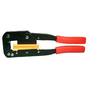
The crimp tools are common:
https://www.frys.com/product/1922804
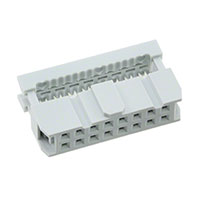
IDC Sockets 16-pin (pin pitch 0.1 inch)
https://www.digikey.com/product-detail/en/assmann-wsw-components/AWP-16-7240-T/HHKC16H-ND/5031953
Assman Part number AWP 16-7240-T
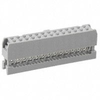
IDC Sockets 26-pin (pin pitch 0.1 inch)
https://www.digikey.com/product-detail/en/assmann-wsw-components/AWP-26-7240-T/HHKC26H-ND/5011313
MPG Wiring and Interface
MPGs (Manual Pulse Generators) should be connected directly to KFLOP for guaranteed real-time response (not USB based or connected to the PC). MPGs are handled by a C Program that monitors the MPG and creates motion based on the MPG Encoder changes and switch selections for axis, speed, and so forth. See the MPG C Program Examples. Here is a Discussion with other links.
https://groups.yahoo.com/neo/groups/DynoMotion/conversations/messages/12287
https://groups.yahoo.com/neo/groups/DynoMotion/conversations/messages/331

Interfacing NPN Devices to KFLOP IO
NPN devices (open collector)operate as a switch to GND and can be interfaced to KFLOP using a pull up resistor as shown below. When the transistor switches to 0V the KFLOP IO Pin is driven low. The transistor will need to sink ~3ma. When the transistor is off (open circuit) the resistor pulls the IO Pin to 3.3V. Note even though some KFLOP IO Pins can tolerate 5V pulling them above 3.8V should be avoided when possible so the 3.3V supply is used. This technique will only work with KFLOP IO Pins that do not have pull down resistors (JP7 and JP5). In some cases a 0.1uF Ceramic capacitor connected close to KFLOP might be added in parallel with the resistor to filter noise. Cable shielding connected to KFLOP GND on the KFLOP end only is recommended. Note that in noisy environments this technique may couple noise into KFLOP so opto isolation should be used instead.

Multiplexing Encoder Inputs to KFLOP JP4 and JP6
If KFLOP JP7 and JP5 are used for other purposes the encoder inputs can be multiplexed to KFLOP JP4 and JP6. There is an option to multiplex encoders 0-3 from JP7 to JP4 and another option to multiplex encoders 4-7 from JP5 to JP6. See the MuxEncoders.c for an example.
Note the JP4 and JP6 IO are 3.3V inputs and shouldn't be driven hard (more than 10ma) above 3.8V. This is not usually an issue as most encoders or RS422 drivers don't do this. The inputs also have 150 ohm termination.
The following line of code might be added to your Initialization C Program. It needs to be executed once to multiplex the encoders after any power cycle. Encoders 0-3 will then be input on JP4 and 4-7 will be on JP6. Both JP4 and Jp6 have 10 IO bits. The 4 encoders will appear on the first 8 IO bits. 2 bits for each encoder's A B channels in order. So for example Encoder #0 will appear on JP4 IO16 (Pin5) and IO17 (Pin6)
// Mux encoder inputs from KFLOP JP7 & JP5 to JP4 and JP6
FPGAW(ENC_NOISE_FILTER_ADD) = ENC_0_3_JP4 + ENC_4_7_JP6 + ENC_NOISE_FILTER_DEFAULT_VAL;
JP4 and JP6 have +5V available on Pin1 and GND on Pins 8 and 9 that might be used to power 5V encoders.
Axes Servo Tuning and Trajectory Planner
Basic Servo Tuning Overview
Once an axis is configured and proved capable of holding a position it is ready to be tuned and optimized. Most often a small value of P Gain only is used to show the servo is functional and can hold position. The Servo may be very weak and inaccurate but will be functional.
Every system is different and the tuning parameters are interactive in a manner that usually doesn't allow parameters to be determined one at a time. Rather after one parameter is changed it may be necessary to revisit the other parameters.
In general higher gains will reduce errors and improve accuracy, but tend to make the system more unstable. So the general idea is to increase gains to reduce errors as much as possible but still have a stable system.
Often during tuning the system may go unstable. In fact, it is normally intentionally driven to instability to find its limits for a certain parameter. This can result in a violent oscillation or worse so one should be prepared to quickly disable the Servo. If an appropriate Max Following Error is used the axis can be automatically disabled before the oscillation becomes too violent, yet not disable when performing a normal test.
KMotion.exe allows you to change any axis parameter on the Step/Response, Config, or Filters Screens then simply push "Move" to see the effect of the change. Note that as performance improves the errors will become small and difficult to see on the Position Plot without Zooming in (Left click drag) so changing the plot type to plot the error is useful.
The overall process normally goes something like this:
- Select a Test Move Size and Motion Profile. See Also
- Select Max Limits to allow for the Test. See Also
- Determine maximum level of P Gain
- Determine maximum level of D Gain (with Low Pass Filtering) See Also here and here.
- Determine new maximum level of P Gain now that D Gain increased stability
- Add I Gain to improve accuracy and remove steady state errors. See Also
- Add Feed Forward to reduce errors
Torque Servos vs Velocity Servos
+/-10V Analog Amplifiers usually come in one of two varieties: Torque or Velocity. Torque mode amplifiers consider the input command as a Torque Command and work to generate the commanded Motor Torque. Velocity mode amplifiers consider the input command as a Velocity Command and work to generate the commanded Velocity. Its important to understand what type of Amplifiers you have.
Velocity Mode Amplifiers need some form of feedback going to the Amplifier in order for the drive to know the current velocity. This might be a digital encoder or an analog tachometer.
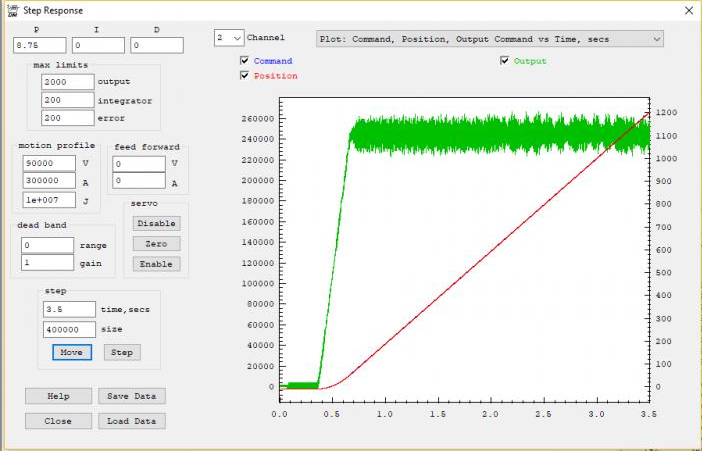
Its easy to tell if you have a Velocity Mode Amplifier by looking at a plot of a move on the Step Response Screen. The Output (green plot with right scale) will be proportion to the motor velocity. When moving at constant speed the output will be relatively constant. See in the plot below the output (green) remains at a relatively constant ~1100 DAC counts while the position (red) ramps at a constant slope of the 90000 count/sec rate:
Velocity mode amplifiers can be relatively easy to tune using only P (Proportional) Gain. Additional Gains and filters can be used for best performance but using only P Gain will often result in reasonable performance and a stable system (unlike Torque Mode Amplifiers).
As an example consider controlling the speed of a car using only Proportional Gain as it approaches a target (Stop sign). Consider a P Gain of 0.1 where at 1000ft from the stop sign we command 1000 x 0.1 = 100MPH. Then at 100ft we command 10MPH. Then at 10ft we command 1MPH. This results in a nice, smooth, exponential approach, without overshoot.
Contrast this with controlling the acceleration (torque) of a car using only Proportional Gain as it approaches a target (Stop sign). At large distance we apply maximum acceleration. Although as we approach the stop sign we reduce acceleration, we continue to accelerate and speed continues to increase until we pass the stop sign. Torque mode servos are inherently unstable. P only gain only works at all if there is some friction (the car is dragging a sled which slows us down with less torque).
Acceleration Mode Servos may or may not have any feedback. If they have feedback it is usually used only to commutate a brushless motor. In the plots the Output (green) will have large magnitude when the Position (red) is accelerating, where the plot has curvature (changing slope).
Acceleration mode Servos are unlikely to work well or at all with only P Gain. Some form of damping or lead compensation will usually be required to get a stable system. D (derivative) Gain (or a lead compensator) should be included with the P Gain to help stabilize the system. D Gain can be increased to make the system more stable up to a point. After some point the additional D Gain will make the system more unstable. and should be reduced.
When using D Gain (or lead compensation) the quantization noise (steps) in the encoder position can cause spikes in the output. For example a D Gain of 100 will cause a spike of 100 counts in the output whenever the input changes suddenly by 1 count. If the spikes are very high amplitude and short duration, the Amplifier may not handle them in the expected manner. A low pass filter can be used to widen and reduce their amplitude allowing the amplifier to handle them more effectively. Typically a 2nd order low pass filter of 500Hz Q=1.4 is used. The last filter is normally used so it is applied to any Feed Forward. Such as:

Velocity, Acceleration, and Jerk
The KMotionCNC parameters are used for 2nd order (infinite Jerk) coordinated motion paths. These are GCode G1,G2,G3 continuous paths. The units are in Inches (or in some cases degrees). Note there is an Option in KMotionCNC "Rapids as Feeds" where these parameters will also be used for Rapids. But this option should only be used for highly non-linear Kinematic Systems which can not take advantage of faster/smoother 3rd order point to point straight line Rapids.
The Step Response Screen always performs 3rd order motion but 2nd order motion can be simulated by temporarily setting the Jerk to a huge value (1000X the acceleration value). In general reducing the Jerk value will result in longer times to perform motions, but often the improved smoothness will permit higher maximum accelerations and velocities to be used resulting in overall shorter motion times. An analogy might be how you might stop more quickly in a car, without skidding or spilling your coffee, by applying the brakes harder in a more gradual manner rather than slamming on the brakes.
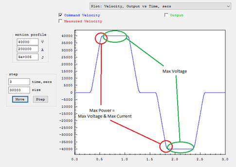
Make sure when testing the size of move is long enough for full acceleration and velocity are achieved. A common mistake is to have Acceleration or Velocity Settings set to too high for your system but when testing a short move there is no indication of a problem. The plot mode of Velocity Output vs Time can be helpful to verify full Velocity is being achieved.
For example to accelerate to 700,000 counts/sec at an acceleration rate of 700,000 counts/sec^2 would take 1 second. And then to slow back down would take 1 more second. So at least 2 seconds of motion would be required to get to full speed. A 100,000 count move (2 inches for a system with 50,000 counts/inch) takes much less time than that. Furthermore with a relatively low Jerk setting (1e6). This means the acceleration will be applied gradually over 0.7 seconds. This means an even much longer time and distance would be required to achieve top speed.
Here is the method to follow to find 2nd/3rd order motion profile limits:
(note every system is different and will vary based on resolution, motor size/type, mass, etc...)
1 - Find Max Velocity at low Acceleration and infinite Jerk
Choose a Velocity to test (ie V=100000 counts/sec)
Set a moderately low Acceleration Time of 1 second (A = V/1sec = 100000 counts/sec^2)
Set very high Jerk so Acceleration is applied almost instantaneously in 0.001 sec (J = A/0.001sec = 1e8 counst/sec^3)
Test a very long move 20 inches if possible (for resolution 50000 counts/inch, 1,000,000 counts)
Plot Velocity, Output, vs time to see if V is actually obtained
If the motion was successful repeat all above with higher V, if not try lower V
Once Max V is found reduce by some margin (ie 20-50%)
Note you may decide on lower speed for other reasons (safety, vibration, noise, wobble, shock, etc....)
2 - Find Max Acceleration for your system for the chosen Velocity
Using the V found above increase A (keeping Jerk high in the same manner) until the system fails/faults/excessive shock, etc...
Once Max A is found reduce by some margin (ie 20-50%)
These V and A Values are now known good values for your system and can be used for 2nd order motions such as KMotionCNC Trajectory Planner or Mach3 Motor tuning. Note units will need to be converted (counts to inches or mm, time from seconds to minutes depending on the App)
3 - Find optimal 3rd order Jerk limited motions.
The previous result from Step #1 and #2 used nearly infinite Jerk where Acceleration forces were applied nearly instantaneously. By reducing Jerk smoother motion should be possible.
Set Jerk so it is applied over 20ms (ie for A=200000 J = A/0.020 = 1e7
Test to see if motions are smoother. With closed loop systems the Position Error Plot can be used to see if the motion has less error and is smoother. Open loop system will require you to hear the difference.
Increase/decrease Jerk to find the optimal value. Note reducing Jerk a lot will of course make the system very smooth, but will also be much slower using less acceleration and velocity which is undesirable. So the highest Jerk possible should be found that still provides some smoothness.
Reducing Jerk only will always make the system slower with less performance (but hopefully significantly smoother). It is usually then possible to increase Acceleration and Velocity somewhat to achieve even higher performance than what was possible with infinite Jerk while being as smooth or smoother.
4 - Reduce Max Following Error Limit to small value
Axis Resolution - counts/inch (or counts/mm)
- counts or steps per motor revolution
- any gearing or belts and pulleys involved between motor and drive mechanisms
- lead screw pitch, rack and pinion tooth pitch, drive belt radius, etc.
For example consider a Stepper Drive with:
3200 steps per motor rev
2:1 gear reduction from motor to lead screw
0.2 inch lead screw pitch
Axis Resolution = 3200 step/motor rev x (2 motor rev/ screw rev) / (0.2 inch / screw rev) = 32000 steps/inch
To determine whether your assumptions and calculations are correct perform a test. Command as large of a move as convenient and measure the actual distance moved with a ruler. For example in the axis described above you might command a move of 320000 steps. This should result in a motion of:
320000 steps / (32000 steps/inch) = 10 inches.
For KMotionCNC set the Axis Resolution in the Tool Setup | Trajectory Planner Screen | Axis Parameters | cnts/inch. Note units must be in units of inches. If your resolution is in mm units multiply by 25.4.
For Mach3 enter the Axis Resolution in the Configuration | Motor Tuning Screen. Make sure the setup units (not GCode units) match the mode of your values.
Servo Dither/Hunting - (oscillation around zero error)
Lowering gains will usually help at the expense of performance. However in many cases more than acceptable performance can be achieved with lower gains so one should consider if the higher gains are really needed.
KFLOP has a Deadband Gain and Range feature that can basically be used to tell the servo to not attempt to correct small errors (treat the errors as zero), or to try to correct them less aggressively (with a Gain less than 1.0). See here for more information
Unfortunately adding Deadband doesn't always help the servo "sit still" and may actually increase the size of the dither depending on the dynamics.
Note that when the servo is commanded to a non integer position ie 999999.7 encoder counts without deadband the servo will always be making corrections. The best the servo can do is dither between encoder positions 999999.0 and 1000000.0. With an error of either -0.7 or +0.3. A servo with Integrator gain will guarantee the average is 999999.7
If dither is still a major problem a C Program might be used to monitor things and change settings under certain conditions to reduce dither. See the example AntiServoDither__ALL.c which monitors for small errors for a period of time and if so reduces or turns off Integrator gain.
Noisy GCode - Trajectory Planner Smoothing

Arc "faceting" - Trajectory Planner - Collinear Tolerance
I Gain/Max Limit Integrator
I (Integrator) Gain can be used to eliminate persistent errors. In fact any Integrator Gain at all guarantees the average error over infinite time is zero. Without I Gain a system might have a small error that does not create enough output to overcome stiction to make a correction. In such a case the error could persist forever. Not so with any Integrator Gain. Any error will be integrated and ramp the output higher and higher until eventually there will be a correction. That assumes the Integrator or Output doesn't saturate or reach their programmed limits. The rate the output ramps (or sums) is dependent on the size of the error and the I Gain value. The Error x I Gain is summed every servo sample (90us). This is why I Gain values are often small numbers (0.0001 - 0.01 typical range). There is no guarantee that the position doesn't over shoot the target Destination. In fact it is likely as as any error (area) under the trajectory will always be balanced by an equal area over the trajectory. Too high of I Gain will make the system unstable.
Another case where I Gain is useful is when moving at high speed with a Velocity Amplifier. To move at high speed a significant amount of output is required. Without I Gain a significant amount of error could be required to provide this Output (ie Error x P Gain = Output). With I Gain the Integrator will eventually ramp up to provide any Output necessary to move at the desired speed driving the error to zero.
Integrators have an issue often referred to as "Integrator Wind Up". This issue usually doesn't arise under normal conditions. However if something is preventing the servo from making a correction such as forcing the position away from the target for a sustained amount of time, or disabling the amplifier, the Integrator will integrate to a huge unlimited value. When the force is removed or amplifier re-enabled, the Integrator will likely cause a violent motion and overshoot. Max Limit Integrator can help to minimize this issue by limiting the amount the Integrator can ramp up to. So the Max Limit Integrator Value should be set at the minimum value that can still allow the Integrator to function in normal circumstances.
Typically there are two cases that should be considered when determining the Max Limit Integrator.
- The amount of output expected to be required to overcome any stiction, friction, or other forces (cutting, gravity, etc...). This is often not a large value and can be estimated or can be observed from the Step Response Screen (green plot right side scale is the output) when making a move.
- The amount of output required to provide the output needed to move at speed. It is important to note that D Gain provides a damping or drag effect on the Output. So the Integrator must be able to ramp up to a sufficient level to overcome the damping or drag effect and still provide enough output to move at the commanded speed. For example:
Assume:
- Commanded speed of 500,000 counts/sec
- D Gain of 35
- Output required to move at speed is 1800 DAC Counts
- Servo Sample Time of 90us
Damping effect = Speed x D Gain x Sample Time = 500000 x 35 x 90e-6 = 1575 counts
Required Integrator Value = 1800 + 1575 = 3375
So to provide some margin an Max Limit Integrator Value of 3500 might be used.
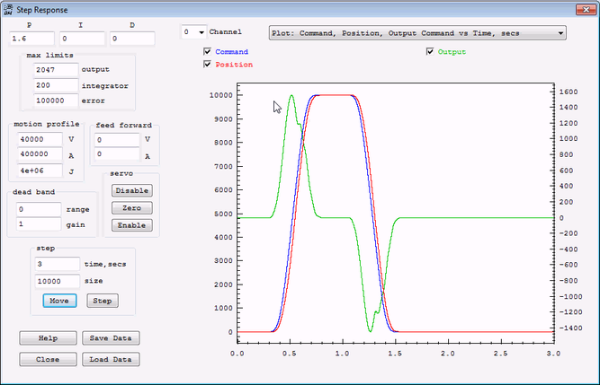
Max Limits - Error
Max limits error can be helpful to have your system respond less violently in the abnormal event where an excessively large error occurs. Normally with a properly tuned system following errors should be small. Setting a Max limits error can cause the servo to treat errors beyond a specified limit as if they were only the size of the limit and therefore respond less so than they would otherwise. The max limits error is normally set to a value so it is not limiting under normal circumstances.
The Plot below shows a situation where a small max limits error combined with a low P gain severely limits the Output. In the plot below a large move (10000 counts) at a high speed (40000 counts/sec) is commanded. Only P Gain (0.2) is used to provide the Output (green). The max error limit of 200 combined with the low gain (0.2) limits the output to only 40 DAC counts. Even as the true error increases to many thousands of counts, the servo is told to ignore the amount over 200. So the output can never exceed 40 DAC counts. The 40 DAC count limit means that the Axis is therefor not capable of providing the output necessary to keep up with the commanded motion. The axis does the best it can with the limited output, and only does a fraction of the desired motion.

After increasing the max limits error the Output (green - right scale) now goes to a much higher value (900), and the Position (red) follows the Command (blue) to a much better degree.
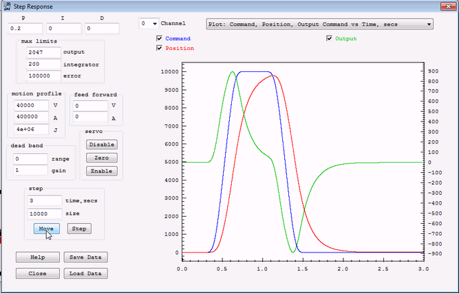
Increasing the P Gain to 1.6 also applies more Output sooner and the Position follows the command still better.
Lead Compensator vs Derivative Gain
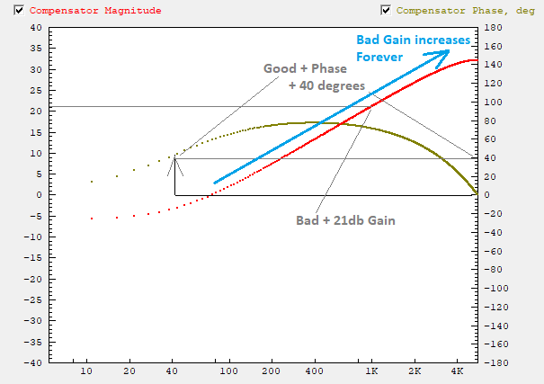
Derivative (D) Gain is often used to help stabilize a system. It helps to think in the Frequency Domain to help understand how the two forms of compensation help. Please read below and this for more information on the Frequency Domain. Both Compensation methods add positive phase to help stabilize the system. Unfortunately both methods increase gain at higher frequencies possibly causing the system to go unstable at higher frequency. A Lead Compensator provides the benefit of positive phase but without as much gain increase at higher frequencies. This figure shows a simplified Gain Plot comparison:

Here is a Bode Plot of a P=0.5 D=20 Compensator. Note the KMotion.exe Bode Plot Screen has the capability of plotting the Frequency Domain Response of the PID+Filters Compensation. Assume we desire positive phase to be added at 40Hz. Notice the positive phase of 40 degrees at 40Hz which is good. However the Gain increase in the 1KHz region of about 21db which is bad.
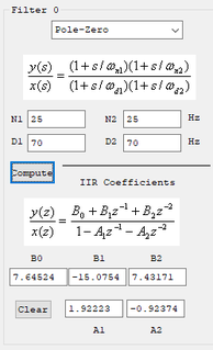
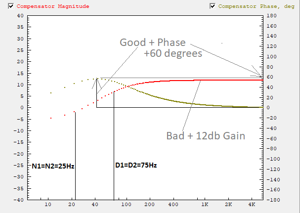
Here is a Bode Plot of a P=0.5 N1=N2=25Hz D1=D2=70Hz Compensator. Assume we desire positive phase to be added at 40Hz. We choose N1 N2 and D1 D2 to surround the frequency where the positive phase is desired. Moving them further apart will increase the amount of positive phase but also increase the added Gain. Notice the positive phase of 60 degrees at 40Hz which is good. However the Gain increase in the 1KHz region of about 12db which is bad. However both are improvements over the D Gain compensator.
Bode Plots
A Bode Plot is a powerful tool for characterizing and providing insight into a dynamic system. It can help determine closed loop stability, bandwidth/performance, resonant frequencies, and more. It is entirely based on the system being linear. Linear in the sense that if the amplitude of some input signal is changed then the output signal will change proportionally as well. Unfortunately most systems are not entirely linear. Stiction, backlash, encoder quantization, amplifier saturation, and other effects are non-linear. For example driving a system with a signal too small to overcome stiction will result in no output at all whereas a larger signal will result in some output. This is clearly non-linear behavior. It would be nice to use a technique that handles non-linear systems but basically none are known.
A Bode Plot is made injecting a stimulus to the system and observing how the system responds. For the reasons of non-linearity it is very important to perform a Bode Plot measurement using a representative level of stimulus similar to what the system will actually have during normal operation. If the Stimulus is not adjusted properly the result is likely to be completely invalid. Additionally the system should be reasonably tuned and stable so that it is responding in a reasonable way to the stimulus. If the system is unstable or very poorly tuned the result is likely to be completely invalid.
You might think of it somewhat like shaking a box to determine what is in it. You should shake it with enough intensity and at frequencies to get some reaction, but not so high of intensity to break or distort the object inside.
To create a Bode Plot use the KMotion.exe Bode Plot Screen. First select Plot: Time domain - Command, Position, Output vs Time and adjust the Amplitude and cutoff Freq until there is small but significant Position (red) changes (ie 50 encoder counts), at a frequency low enough that the Position at least somewhat attempts to follow the Command (blue), and where the Output (green) is not near saturation for the Drive being used.
After the Stimulus/Noise Injection settings are set switch to Plot: Open Loop - Magnitude and Phase vs Frequency. Set the number of Samples to average (ie 20) and perform a Measurement. See here for more information.
Links to other Information on Tuning and Bode Plots
umich.edu Introduction section Control Frequency
Kollmorgen Use Control Theory to Improve Servo Performance 230712.pdf
Problems and Resolutions
General
- Dealing with noise on inputs. If you experience issues with inputs misreading, the issue may be noise. This page provides examples on what might be causing noise issues and examples of how to possibly deal with noise.
- Other
Software-Specific Problems and Resolutions
- Place links to pages explaining resolutions to problems that are largely software-related here
KFLOP User C Programs Compiling/Launching Slowly because of Windows Defender
Hardware-Specific Problems and Resolutions
- Place links to pages explaining resolutions to problems that are largely hardware-related
Step/Dir Drives lose 2 Steps for each pair of Direction Reversals
Applications and Projects
- Place links to pages that explain how you accomplished your particular project. Write clear explanations that provide background on what you did and how you did it.
Tool Changer - router linear 4 Tools - C Program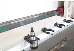
Part Zero & Tool Height Touch Plate
Driving Hobby Servos
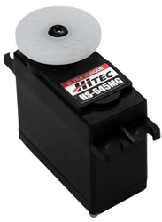
HiTec Type
Electrical Discharge Machining
EDM (wikipedia)is a method of cutting materials with high precision and detail. Dynomotion Motion Controllers work well for EDM because of the ability for feedrate to be dynamically controlled including reversal along cutting path.
Information on BAXEDM Arc Generators used with KFLOP
How to convert a milling machine to a 3D printer in 3 easy steps
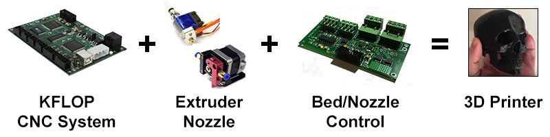
More information here.