I am having a strange problem, I thought at first
that it was an issue with voltage levels between KFLOP
and the drives (step/direction signals) but it seems to
be a grounding problem.
Background:
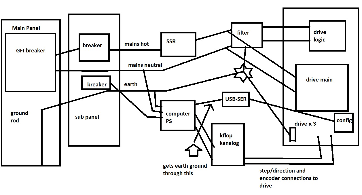
I am using brushless servos where the drives are
connected to mains. The drives have separate inputs for
the servo power supply and for the drives logic power
supply. The drive logic is connected to a power line
filter as recommended in the drives instruction manual.
The drives metallic mounting plate is at earth ground
and there is a star earth ground connecting the drives
to the breaker panels earth ground. This is also the
earth ground for the casting of the machine.
How the problem presents itself: I command a
movement that amounts to 1000 steps. It misses steps and
moves maybe 950 steps. I know this from the drives
encoder output which is connected to the kanalog encoder
input.
The drives have a serial interface that's used for
configuring them. Its a TTL level serial interface and
the drives came with a level shifter dongle that I have
connected to a USB to serial converter. If this is
plugged in the drives work perfectly. The computer gets
earth ground from being plugged into the mains. It
shares this with the kflop through USB. So the KFLOPS
0v is actually earth ground. It also provides earth
ground to the drives via the USB to serial interface.
If I connect the USB to serial interface to the
drives, then they work perfect and don't miss any
steps. The USB to serial interface is putting earth
ground which is also kflops signal ground into the
drives.
I tried isolating the computer using an isolated
power supply that didn't give the computer earth ground
and this made things worst.
So should I tie the drives signal ground to the kflop
ground?
-Colin