Hi Br. Danchik,
Very Strange. What type of drive do you have on Z? What are your Trajectory Planner Settings? Post your Initialization C Program. Can you duplicate the problem with a small fragment of GCode? If so please post it.
Regards TH
| Group: DynoMotion |
Message: 11086 |
From: stuntready |
Date: 2/15/2015 |
| Subject: Re: Strange Z axis behavior |
Motor on Z axis is servo motor with encoder and servo driver (step dir operation). all 3 motors are the same, and I am sure that it's not motor problem. I made a couple of new parts as experiment and it's 100 % something like Z axis move is buffered and goes later then it have to.
Also X and Y axis with same motors configured as closed loop with glass scales operates briliant. Only Z axis that is open loop step dir operates faulty
May be i should install glass scale to Z axis as well ?
I will post all you asked on monday.
|
|
| Group: DynoMotion |
Message: 11087 |
From: Tom Kerekes |
Date: 2/15/2015 |
| Subject: Re: Strange Z axis behavior |
Hi Br. Danchik,
You shouldn't need glass scales to get your Axes to move correctly/quickly. You might check your Drive settings to see if there is some max velocity, acceleration, Jerk setting that is too low.
Regards TK
| Group: DynoMotion |
Message: 11097 |
From: stuntready |
Date: 2/16/2015 |
| Subject: Re: Strange Z axis behavior |
Thx Tom for your help.
I thoght so as well at the very begining,but if axis motion are so slow as you predicted, during the milling we will see something like "overshot" on trajectory changes, actualy I know how it looks like during milling, but it is not, as well as drive setting (V, A , J) are alsmot 20 x higher the configured in kflop. Also I runned same G-code with twice reduced V and A settings, same results, absolutly no difference.
Also I have made a bunch of experiments, Z axis lates some how, it constant lating during all trajectory.
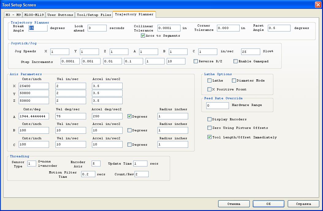
I have atached trajectory settings and C init program. Ataching g-code is useless, it is tested on other machine, also any G-code with 3D surface if 3 Axs are moving at once - fails
|
|
|
|
| Group: DynoMotion |
Message: 11098 |
From: Tom Kerekes |
Date: 2/16/2015 |
| Subject: Re: Strange Z axis behavior [2 Attachments] |
Hi Br. Danchik,
I don't see anything unusual with your C Program or Trajectory Planner Settings. I can't think of any reason Z would be delayed.
You might try temporarily removing the A rotary Axis from the Coordinate System to see if that is somehow causing the problem. As that is the only thing somewhat unusual that I see about your configuration.
What happens if you run at a very much reduced FRO? ie 0.10. Is the path different and more correct?
I don't understand why you say limited Velocity in the drive would cause "overshoot". I would not expect that to be the case.
Please include any simple GCode so we are clear about what you are doing, what should be expected, and what is the actual result.
You might use our example C program called CaptureXYZMotionToFile.c to capture the actual trajectory generated when running the simple GCode to see if the problem is in the trajectory or somewhere else (ie. Servo Driver).
If an encoder (linear or rotary) was added for the Z axis it would be then possible to plot exactly what was occurring.
Sorry for no simple answers.
Regards TK
| Group: DynoMotion |
Message: 11099 |
From: stuntready |
Date: 2/16/2015 |
| Subject: Re: Strange Z axis behavior [2 Attachments] |
Thx for your help Tom, no simple unswers is ok, but to clerify everyting I need to prepair and test all you asked for, it will take me a couple of days. I will provide simple G-code as well, also I will try to capture motion, hope it will help.
When i told you about "overshot" i meant accel lack, not velocity. Anyway velocity and accel of servo drive is ok.
BTW, as I understand PID corrrection as well as filters e.t.c. are calculated in FPGA.So, is there any difference (delay) if destonation signal goes through servo flow or directly to axis output? If it is possible somehow - I can check this as well.
Thx for your help again. br. Danchik
|
|
| Group: DynoMotion |
Message: 11100 |
From: Tom Kerekes |
Date: 2/16/2015 |
| Subject: Re: Strange Z axis behavior |
Hi br. Danchik,
The PID algorithms are actually performed in Floating Point in the DSP not the FPGA. But regardless your Z axis is open loop so PID and Filters don't apply at all.
Regards TK
| Group: DynoMotion |
Message: 11106 |
From: stuntready |
Date: 2/18/2015 |
| Subject: Re: Strange Z axis behavior |
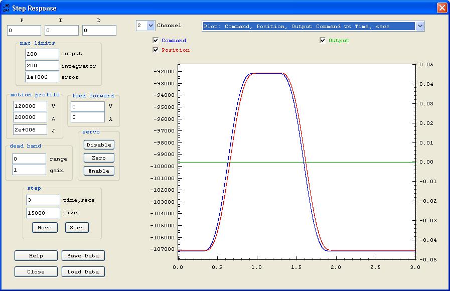
Hi Tom, I didn't have anought time make milling tests, but I have installed glass scale. Please take a look at the atached screen, you can see that Z drive is moving as comanded.
I will report milling test reslults asap.
Danchik |
|
|
|
| Group: DynoMotion |
Message: 11108 |
From: Tom Kerekes |
Date: 2/18/2015 |
| Subject: Re: Strange Z axis behavior [1 Attachment] |
Hi Danchik,
Actually I think that clearly shows the problem. Notice the following error of ~1000 steps!! I don't know what your system resolution is but I'm guessing that is huge.
Notice also this corresponds to a delay of ~25milliseconds and is maintained for hundreds of milliseconds without being corrected.
Could there be some "smoothing" option or something in your drive that would introduce such a lag? Or simply the gain and performance in the drive is extremely low? Any Integrator gain in the drive would normally not allow such a huge error to persist for such a long period of time.
I could see how if you were to go closed loop that KFLOP could reduce the error by advancing the commanded position to compensate. But it would make more sense to correct the problem in the Drive. It may be that your XY axes have the same issue but it is being somewhat compensated for by the closed loop feedback.
In the future please zoom in (left click drag), include a plot of error, or save and post the data so we can re-plot as we desire to see things more accurately.
HTH Regards TK
| Group: DynoMotion |
Message: 11110 |
From: stuntready |
Date: 2/18/2015 |
| Subject: Re: Strange Z axis behavior [1 Attachment] |
Hi, thx for your answer,
My Z axis drive rolution is 0.0005 mm, glass scale used for feedback is 0.005 mm resulution, ch2 input gain is 10 so thats why I think there is a little lag in plot. Anyway there is no closed loop enebled on the scrren I provided.
I have enabled closed loop, and max folowing error with the same settings is less then 120 steps = 120/10 * 0.005 = 0.06 mm, quite good I think.
Also, I milled small 3D surface with all 3 axis closed loop enabled and problem is almost solved (I used small I gain so Z axis was little bit slowed). But the difference is so huge, and surface is realy almost fine... this makes me realy confused, and driver problem seems to be not possible...
Second thing that makes me doublt in driver problem is that 3D surface have constant lag during all trajectory, if there was some smoothing, trajectory should lag on changes and then go stable on straight line segments, but it is not. It's easy to see this problem if you will try to mill concentrate circles in one way on 45 degree to XY plane flat surface, you will see constant Z lating on any feed rate.
Anyway all you are talking about drive settings looks possible, so I will check everything once more and provide more information.
Thx again for your help.
Danchik
|
|
| | | | | | | | | |